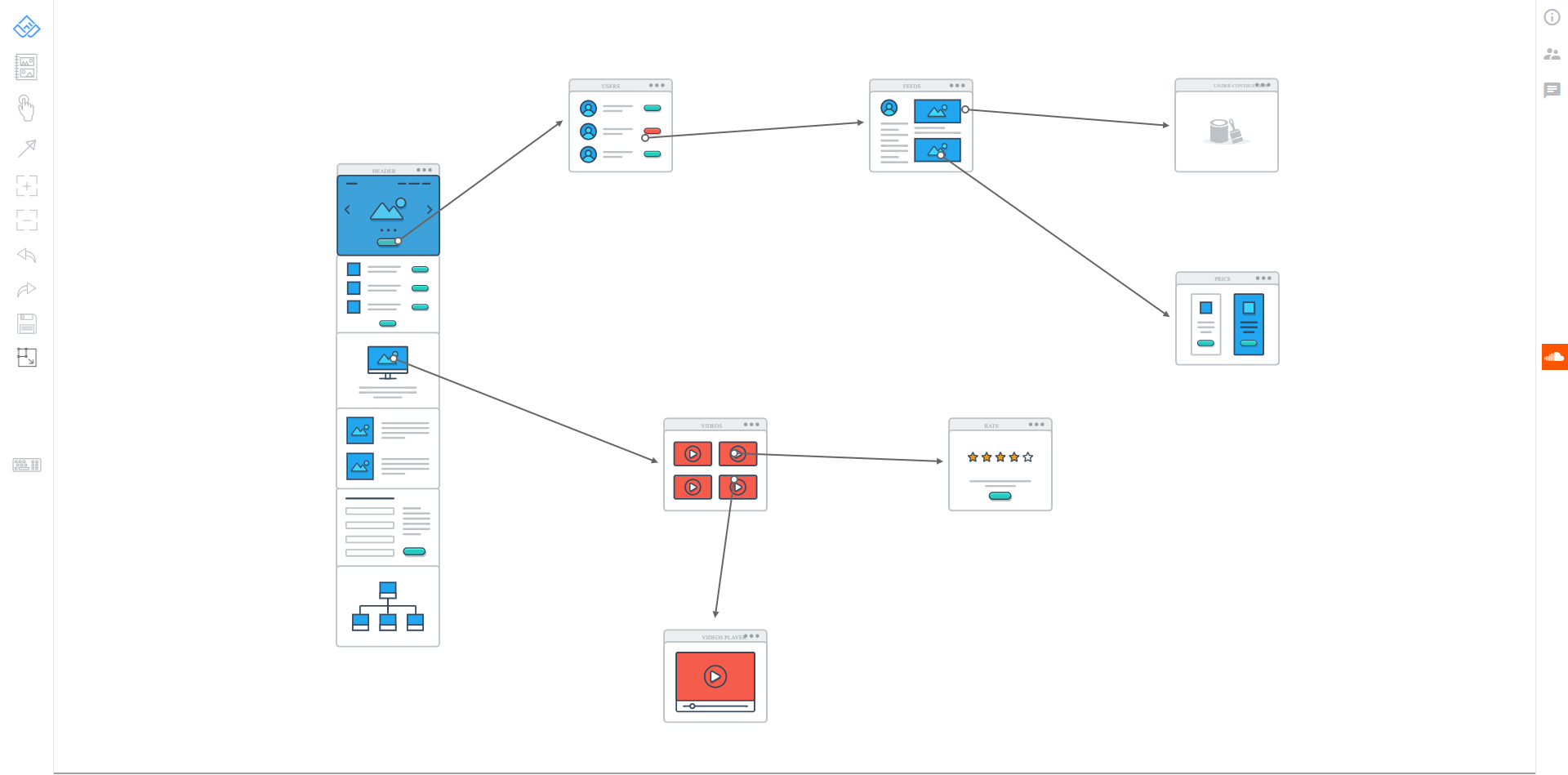
20+ software user flow diagram
Annual or monthly commitment 2. This axis is useful as itll help you chart your project progress across.

15 Awesome Css Flowchart Examples Onaircode Flow Chart Software Development Life Cycle Workflow Diagram
User Class.

. Provide structure before coding begins Visualize requirements as you build on existing work. The pipe flow equations are well-accepted in the field of fluid mechanics and can be found in many references such as Cimbala and Cengel 2008 Munson et al. As you are into the workspace of EdrawMax drag the symbol that you need directly onto the canvas.
Click the icon of Basic Electrical to open the library that includes all symbols for making electrical diagrams. A potential scenario in which a system receives an external request such as user input and responds to it. Creately Visual Tools to Get Things Done Connect People Docs Projects and Data.
An extensive collection of electrical diagram templates can be found in the Electrical Engineering category. The friction factor for turbulent flow is found using the Colebrook equation which represents the Moody diagram. Developers and engineers use these diagrams as a framework to support their work in many ways.
Share your work as a web-based link attachment PowerPoint image. Often used in the plural to suggest situations where a piece of software may be useful. Software Engineering Control Flow Graph CFG Control Flow Software Testing.
It is central part of organization for which software is being designed. A list of the equipment numbers along with a brief descriptive name for the equipment is printed along the top of the diagram. Rules for Data Flow Diagram.
A call graph also known as a call multigraph is a control-flow graph which represents calling relationships between subroutines in a computer programEach node represents a procedure and each edge f g indicates that procedure f calls procedure gThus a cycle in the graph indicates recursive procedure calls. F is the Moody friction factor. Figure 13 shows that each major piece of process equipment is identified by a number on the diagram.
The Use Case Diagram is a UML Diagram where the each use-case specifies the behaviour expected from software from the perspective of end-user and relation as well as provides brief overview for different components concerning interaction between use-case actors and systems. 1998 and Streeter et al. If the new user is a lecturer or an admin the user will get added separately whereas students will get added as a batch.
With the help of a data flow diagram your software team can. The MCU bootloader is a configurable flash programming utility that operates over a serial connection on supported NXP MCUs. Triggering event The admin submit a new user account creation activity.
Launch EdrawMax on your computer. Creately is the worlds 1st work management software that runs on a smart visual canvas. The cumulative flow diagram also highlights your project time frame along the X-axis.
The location of these equipment numbers and names roughly corresponds to the horizontal location of the corresponding piece of. Use Case Diagram for Bank ATM System. Enjoy everything in Plan 1 plus exclusive Plan 2 features such as export to Microsoft Flow or Word Excel data visualizer.
The Use-Case Diagram is used to prepare present and understand functional. Complete diagrams faster with multiple users working on the same diagram at the same time. It enables quick and easy programming through the entire product lifecycle -- from application development to final product manufacturing and beyond -- for updating applications in the field with confidence.
Connect the dots across your company keep everything and everyone in sync. 20 1500 Languages 98 11 English French German Japanese Spanish Italian Portuguese Russian Korean Simplified Chinese Traditional Chinese. If you are a beginner you will find that this Visio process flow diagram software has the easiest user interface that makes it easier for everyone to create prototypes and process maps.
The start point of your project is to the left of the graph while the end point is towards the right. Brief description When a new user has to be added to the new system the admin adds him using create new user work flow. A usage scenario for a piece of software.
Capture the increasingly complex flow of information through a system with a data flow diagram. In software and systems engineering the phrase use case is a polyseme with two senses.

Types Of Flowcharts Data Flow Diagram Workflow Diagram Flow Chart

20 Flow Chart Templates Design Tips And Examples Venngage

Communicate Visually At The Speed Of Thought Collaborative Flowcharts Wireframes Sticky Notes And Mind Maps Flow Chart Mind Map Work Space

Pin On Inspiration

Operational Flow Chart Template Unique 55 Fresh Standard Operating Procedure Flow Chart Template Process Flow Chart Process Flow Flow Chart

15 Awesome Css Flowchart Examples Onaircode Flow Chart Software Development Life Cycle Workflow Diagram

15 Awesome Css Flowchart Examples Onaircode Flow Chart Workflow Diagram Software Development Life Cycle
User Flow Diagrams For The Three Primary User Flows In The Peer To Peer Download Scientific Diagram
Flow Diagram Of Master P2p Go Application Here S The Explanation Of Download Scientific Diagram

User Interface Flow Diagram Download Scientific Diagram

11 Awesome User Flow Tools For Ux Design

Gliffy Mind Mapping Tool Mind Map Mind Mapping Tools Free Mind Mapping Tools

20 Flow Chart Templates Design Tips And Examples Venngage Flow Chart Template Mind Map Template Flow Chart

15 Awesome Css Flowchart Examples Onaircode Flow Chart Software Development Life Cycle Workflow Diagram

20 Flow Chart Templates Design Tips And Examples Venngage

Xmind Mind Mapping Tool Mind Mapping Tools Mind Map Mind Mapping Software

20 Useful User Flow Tools Templates Bashooka